
What Are External Dynamic Lists (EDLs)
It is a collection of known malicious IP addresses maintained by various providers, used to block or deny incoming connections from those sources in network security systems like firewalls. These lists help enhance security by preventing access from potentially harmful entities.
This helps organizations dynamically respond to threats by pulling in real-time data about malicious IPs, domains, or URLs without constant manual updates.
Here Is an Analogy
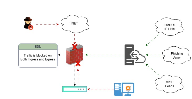
A user clicked a harmful link that redirects traffic to a malicious website. The firewall checks the policy and looks at the External Dynamic List (EDL) profile.
The firewall is connected to an EDL server that contains a text file listing all the banned IP addresses.
A security policy is configured to deny any user traffic targeting those IPs, whether inbound or outbound.
Why are EDLs Necessary?
EDLs allow you to do the following.
- Automate Threat Prevention: Block or allow traffic based on threat intelligence feeds that update automatically.
- Respond to Emerging Threats: Integrate with third-party sources like threat intel platforms, open-source feeds (e.g., FireHOL, Spamhaus), or internal lists.
- Reduce Manual Work: There is no need to update firewall policies every time a new malicious IP/domain is discovered.
- Customize Security Posture: Build rules that reflect the unique threat landscape of your organization.
How To Implement Your Own EDL?
If you want to implement your own EDL server, you need to subscribe to a provider that can provide threat intelligence beyond what the firewall knows.
Or, as a best practice, create your own Local EDL list, like I’m going to show you. If you want to deploy this, you only need a web server, such as IIS, Tomcat, or any variation. Once you’ve done that, you can drop your (.txt) EDL in the correct format. It will look something like this.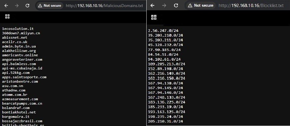
Inbound Traffic
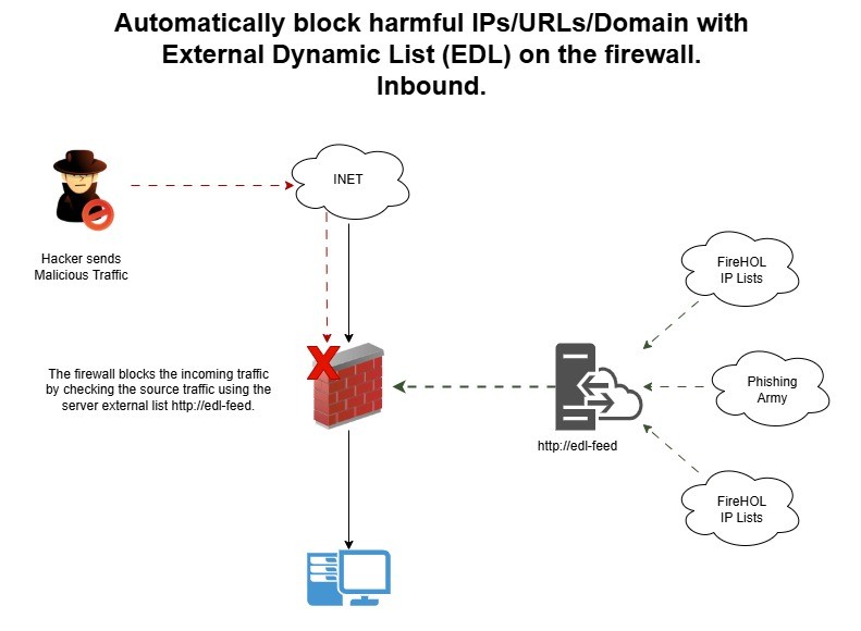
Explanation
- The Attacker tries to send malicious traffic to the firewall.
- The firewall sees the traffic and checks its EDL list from the server.
- The firewall blocks traffic because the EDL contains the attacker’s malicious IP address.
Outbound Traffic
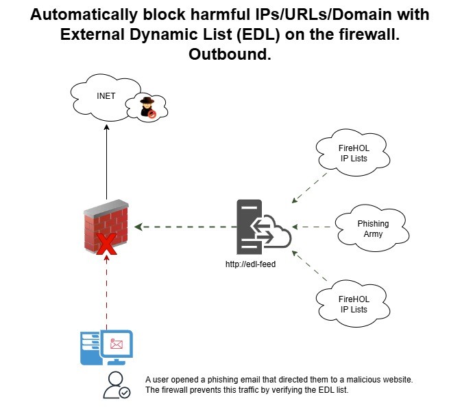
Explanation
- The user opened a phishing email with a malicious URL/domain.
- The firewall sees the traffic and checks its EDL list from the server.
- Traffic will be denied if the URL contains a harmful domain.
Best Practices
- Reference the EDL in all your Security Policies
- Your EDL list can include IP hosts, subnets, ranges, FQDNs, and URLs.
- Validate EDLs regularly — avoid stale or inaccessible lists.
- You can use a backup static list in case the EDL source goes offline.
- Avoid using low-reputation or unverified sources to reduce false positives.
- Monitor EDL status from the dashboard: Monitor > System Logs (search for EDL or URL failures)
Thoughts
External Dynamic Lists (EDLs) really enhance Palo Alto firewalls by seamlessly blending automation with intelligence. Whether you’re blocking known threats or managing access to potentially risky categories. I hope this is informative for you.
Need Help?
If you or your organization are finding it a bit tricky to get this service up and running, we’re here to help! Feel free to give us a call or send us a message, and we’ll help you set it up successfully.
Cheers,